Device Installation
Box Contents
- Enpulse Metering Box
- 1 or 3 current clamps (depending on whether you have one phase or three phases)
- Multi-core cable for voltage measurement and device power supply
Installation Instructions
Important Note
The installation must be carried out by a certified electrician! Green Energy Pal d.o.o. (hereinafter: GEP) is not liable for errors resulting from improper installation. Please contact GEP to recommend reliable certified electricians.
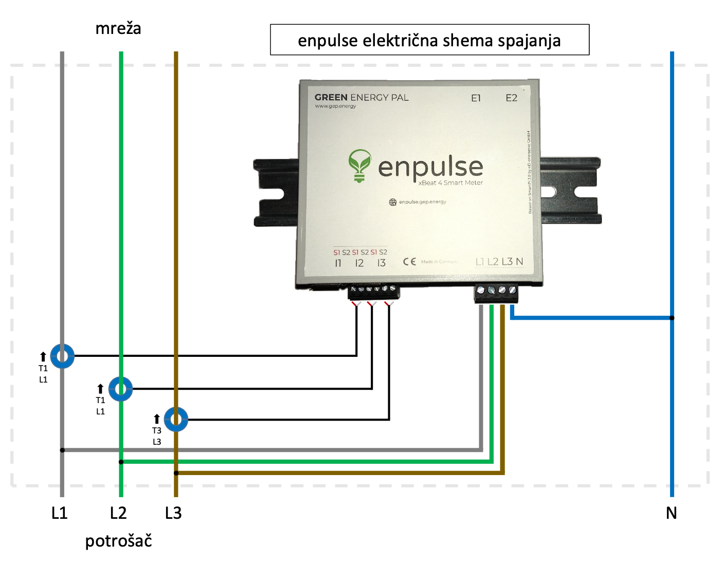
Connection Diagram
Instructions
- Before any installation, the power must be turned off. Attempting to install the device while the distribution cabinet is under power is done solely at your own risk and GEP is not responsible for any consequences.
- Current measurement on each phase must be accompanied by voltage measurement on the same phase. This means that if you connect the current clamps, for example, to phase 1, the voltage taken from that phase must also be on phase 1. Use the markings on the Enpulse Metering Box (viewed from above): The markings S1 S2 designate two wires for current measurement (I1) on phase 1. The L1 marking designates the wire for voltage measurement.
- Placing the current clamps around the main electrical cable (repeat the process for each phase):
- Gently remove the connector with terminal blocks for current measurement from the Enpulse Metering Box (this is the connector with 6 terminal blocks)
- Open the current clamps by gently moving the safety lock
- IMPORTANT! Clamp the main electrical cable with the current clamps so that the side with the YHDC logo and more text is facing away from your installations, towards the utility side. (thus, the side with less text should be facing your consumers)
- Close the current clamps, so that the clamped cable is in the middle. If you have properly closed the current clamps, you will hear a "click" after closing
- Screw the terminal blocks on the Enpulse connector for currents (marking I1 I2 I3). If, for example, you are connecting phase 1, then the red wire goes into the far left of the 6 slots, and the white wire goes into the second from the left of the 6 slots. The last wire (shield) is not connected and you can cut off the protruding tip. You can check if you have properly connected the wires by looking at the letters S1 S2. The red wire should be in the position of the red marking S1.
- Placing the voltage leads for voltage measurement and powering the Enpulse Metering Box (repeat the process for each phase and for neutral):
- Gently remove the connector with terminal blocks for voltage measurement from the Enpulse Metering Box (this is the connector with 4 terminal blocks)
- Connect one end of the wire to the terminal block, being careful which slot you place it in. If, for example, you are connecting phase 1, then the wire should go into the far left slot. Above this slot is labeled L1 (if you look at the Enpulse Metering Box from above)
- Connect the other end of the wire to the voltage
- Repeat the process for all 3 phases and for neutral
- Final placement of the Enpulse Metering Box and connecting the connectors
- Place the Enpulse Metering Box in the desired location
- Make sure that the Wi-Fi network that the Enpulse Metering Box will connect to is active
- Connect the current connector to the Enpulse Metering Box (6 terminal blocks)
- Connect the voltage connector to the Enpulse Metering Box (4 terminal blocks)
- Now that everything is connected and you have stepped back, you can turn on the power in the distribution cabinet
- Check if the lights on the Enpulse Metering Box device are working